Lift & Drag
1 Lift
In this section, we will examine lift and drag in more detail. The force Flift can
be calculated from:
Flift = CL (1/2) ρ V2 S
where:
Flift : Lift (N)
CL : Lift coefficient
ρ: Density of the air
V: True Air Speed or TAS for short (m/s)
S: Airfoil surface area (m2)
In this formula, the coefficient CL depends on the shape and attitude of the airfoil
in the airstream. For a symmetrical airfoil with an angle of attack of zero degrees,
CL equals zero, meaning that no lift is generated. When the airfoils angle of attack
is greater than zero, then the CL value rises accordingly. Angle of attack has a
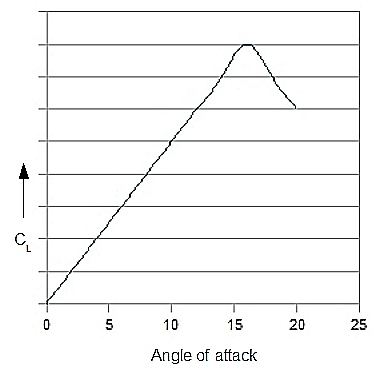
very big impact on the value of CL. The relationship between angle of attack and
the lift coefficient is given in the figure bellow. As can be seen, CL
rises steep with the angle of attack, until the point where a further increase has a counter productive effect. This is the airfoils stall angle. The encountered loss of lift is due to turbelance
and flow separation around the airfoil. So, CL has a maximum value CLmax.
An important observation that can be made about the lift formula is that lift depends
on velocity squared. Where the rotorblades’ airspeed
mainly depends on the speed of angular rotation (RPM), a loss of RPM will inevitably
lead to a major loss of lift. That is why maintaining sufficient and constant rotor
RPM is one of the key
factors when it comes to flying helicopters.
Asymmetrical airfoils are designed to maximise the value CLmax, leading
to greater lift. Such an airfoil will also provide lift at a zero angle
of attack. Asymmetrical airfoils haven’t been used very often because of the greater
forces that come with
them. However, by using stronger composite materials, they
are also utilised in the design of helicopter rotorblades.
2 Drag
2.1 Introduction
In this section, we will again examine an airfoil which moves through an air mass,
as well looking at the phenomenon of drag. Drag is a friction force, which means
it is a force with a direction that is the opposite of movement: it resists movement. When an airfoil moves through an air mass, we can distinguish three different kinds of drag, all with their own distinct properties. These are:
- Profile drag
- Form drag: this kind of drag arises because of the form of the object. Form drag rises with the square of airspeed.
- Skin drag: arises due to friction between the skin and the air mass.
- Induced drag: this is a force component working in the opposite direction of movement
(relative to the air mass), and thus acts as drag. Induced drag only exists when there is
induced flow (= flow that solely
exists because of the downwards acceleration of airflow by the rotor system).
Form and skin drag rise with the square of airspeed, and when combined they define profile drag.
The total drag of an airfoil is built up from both profile drag and induced drag, as shown in the figure below.
Form and skin drag are true drag forces. Induced drag, however, is a different story. It is caused by the effect of induced flow on the direction
of the lift vector. See the explanation in the figure below
Two situations are set out in this figure, one with and one without induced flow. In the latter case, the induced drag is zero, whereas in the former, the RAF angle will increase (increase of inflow angle); that is, its direction is moving in a
way that is almost parallel to the airfoil. This makes the lift vector point backwards
more (relative to the direction of rotor blade movement), and introduces a horizontal force component which is opposite to the rotor movement and thus acts like
a resistant force (red arrows in the figure). We call this component induced drag.
When the airspeed component which is parallel to the rotordisc increases (which simply means
higher rotor RPM), then the inflow angle will decrease, making the
direction of the
RAF more parallel to the rotordisc. As a result, the lift vector of the rotorblade
will change accordingly: it will point up more and backwards less.
Apparently, induced
drag decreases rather than increases with airspeed! Indeed,
induced drag is not
really a friction force.
The total drag of a rotorblade is a function of airspeed. However,
rotor RPM must remain fairly constant in helicopters, and drag forces are, therefore, modulated very little by airspeed. However, drag forces are influenced by angle of attack,
which is dealt with in the next section.
2.2 Drag as a Function of Angle of Attack.
The drag formula reads as:
Fdrag = CD (1/2) ρ V2 S
where:
Fdrag : Drag (N)
CD : Drag coefficient
ρ: Density of the air
V: True Air Speed or TAS for short (m/s)
S: Airfoil surface area (m2)
With their near constant rotor RPM, the most important
way in which rotordrag changes in helicopter operations is due to the change of the angle of attack since
this alters the
attitude of the airfoil, relative to the air mass. Angle of attack,
therefore, has a major influence on the drag coefficient (CD). This relationship is set out in the next figure, which deals with constant airspeed.
Note that the drag coefficient never can reach zero (which would mean that there
was no drag at all). Of course, the blades are designed
to have a low (overall) drag coefficient. At around zero angle of attack, the drag coefficient changes very
little, but when the angle of attack increases, it rises rapidly.
Next topic > Lif/Drag Ratio
|
Helicopter Theory (Paperback)
- This enormous tome provides comprehensive and detailed coverage of every aspect of helicopter theory. The purpose of the
book is to set out for the reader the engineering analyses required to enable the successful design of a rotorcraft. All relevant subjects,
such as vertical flight, forward flight, performance, rotating systems, rotary wing dynamics, aerodynamics and aero elasticity,
and stability and control are covered. They are explained at an in depth engineering level, always accompanied by accurate
mathematical analyses. A good knowledge of mathematics and a degree in engineering are necessary, as these topics are dealt with
extensively throughout the text.
- 1089 pages.
|
|
Principles of Helicopter Aerodynamics (Cambridge Aerospace Series) (Hardback)
- Modern treatment of the aerodynamic principles of helicopters and rotating-wing vertical lift aircraft
- Uses mathematics throughout the text
- Concepts are derived from basic enginering principals
- 864 pages
|
Comments are disabled.